18650 vs 21700 Nickel Strip: What Changes When You Switch Cell Format
.png?token=eyJraWQiOiJzdG9yYWdlLXVybC1zaWduaW5nLWtleV84ODdiMWJmNC1hOWFhLTQ2N2QtYTAwYy0zYTRkZTVjOTFlNWIiLCJhbGciOiJIUzI1NiJ9.eyJ1cmwiOiJJbWFnZXMvSC1UeXBlIEJ1c2JhciAoNSkucG5nIiwic2NvcGUiOiJkb3dubG9hZCIsImlhdCI6MTc4MzQyMTcwOSwiZXhwIjozMDQ0ODYxNzA5fQ.LxqV426w_NdioI9p7Lo8hZDArGupwFmawMebwoNAtxE)
A cell format change usually arrives as a purchasing decision — better energy density, better price per kWh, better availability — and the interconnect is treated as a detail to sort out later. It is not a detail. Moving from 18650 to 21700 changes the geometry your strip has to land on, the current each individual weld carries, and in most packs the total number of welds sharing the load. A strip specified for the old pack will physically not fit the new one, and a strip that only fixes the pitch can still be undersized.
Here is what actually changes, and what to re-specify before you place the order.
Start With the Geometry the Format Names Already Give You
The cylindrical cell naming convention is dimensional, which makes the first part of this easy. An 18650 is 18mm in diameter and 65mm long. A 21700 is 21mm in diameter and 70mm long. A 32700 is 32mm in diameter and 70mm long. Nothing is hidden in those numbers.
The consequence is that a 21700 occupies roughly 1.45 times the volume of an 18650. That extra volume is why the format exists: a 21700 typically carries meaningfully more capacity per cell than an 18650 of the same chemistry generation. It is also why the interconnect changes, because you are now bridging cells whose centres sit further apart, and you are usually using fewer of them.
Pitch Is the First Thing to Re-Specify
Pitch — the centre-to-centre distance between adjacent cells — is what determines where the cut-outs and weld tabs land on a stamped strip. On a close-packed layout the minimum pitch is set by the cell diameter plus whatever clearance your holder or spacer design demands. Going from an 18mm to a 21mm cell moves every centre in the array.
This is the failure that costs the most time. An H-type strip stamped for an 18650 pitch will sit visibly off-centre on a 21700 array by the second or third cell, and completely off by the end of a row. It is not adjustable at assembly. The pattern is cut to a pitch and that pitch is either right or the strip is scrap.
If your holder design is already fixed, measure the actual centre-to-centre distance on the holder rather than deriving it from the cell diameter. Holder wall thickness and the clearance the designer allowed both feed into it, and the real number is often a millimetre or two off the theoretical minimum.
Current per Weld Goes Up, Not Down
This is the part that gets missed. Designers often reason that because a 21700 pack needs fewer cells to hit the same pack energy, the interconnect has an easier job. The opposite is usually true at the weld.
Pack current is divided across the cells in a parallel group. If you rebuild a pack around higher-capacity cells and keep the same pack-level current, you generally end up with fewer parallel paths carrying that current, which means more current through each cell tab and each weld nugget. The strip section between two cells is carrying a larger share of the total than it did before.
So the correct check when changing format is not "is this strip the same as before" but "what is the per-cell current in the new configuration, and does the strip cross-section between adjacent cells still support it". Cross-section is thickness multiplied by the narrowest width the current has to pass through — which on a stamped pattern is the neck, not the full strip width. Our guide to nickel strip current carrying capacity walks through that sizing in detail, and the weight and dimension calculator is useful for sanity-checking the section you end up with.
Thickness and Width Usually Need Revisiting Together
Once per-weld current rises, the two levers are thickness and neck width. Both work, and they fail differently.
Adding thickness raises current capacity in proportion, but it also raises the energy the welder has to put in. Past a certain gauge a resistance spot welder that was comfortable with the old strip starts producing shallow, high-resistance joints on the new one, and the fix is a welder change rather than a strip change. In practice most cylindrical pack builders stay within a familiar band and reach for thickness only when they have already widened as far as the layout allows — we supply from 0.10mm to 0.50mm, and the upper half of that range is where welder capability becomes the binding constraint rather than the material.
Widening the neck raises capacity without touching weld energy, which is why it is usually the first move. The limit is the layout: the wider the conductive path, the less room remains for the cut-out that gives the strip its mechanical flex and, on fuse-type patterns, its fusing behaviour. Widening a fuse neck without recalculating changes the fault current at which it opens, which is a safety-relevant parameter and not a free dimension to adjust.
The Landing Area on the Cell Cap Changes Too
The positive terminal of a cylindrical cell is a raised cap, noticeably smaller than the cell diameter, ringed by the crimp and the gasket. Welding onto the crimp rather than the cap is a classic source of weak joints and, worse, of damage to the seal.
A 21700's cap is larger in absolute terms than an 18650's, but the ratio of usable cap to overall footprint is not identical between formats, and it varies between manufacturers within a format. When you change cells you should re-check the weld tab position against the specific cell you are buying — not against the format in general. Ask the cell supplier for the terminal drawing and dimension the tab from that.
The negative end is more forgiving because the whole base is conductive, but tab placement still matters for consistency: welding near the edge of the base introduces variation in how the two weld pins load the surface.
What to Send Your Supplier
A format change quote goes much faster with four things:
- The new cell's datasheet or terminal drawing — not just the format name.
- The measured pitch from the holder you are actually using, and the parallel and series configuration (2P, 3P, 4P and so on).
- Per-cell continuous and peak current in the new configuration.
- Your welding process and equipment, so the thickness recommendation is one your line can actually weld.
With those, the pattern can be laid out against your real geometry rather than a nearest standard size. We stamp H type nickel strip for 18650, 21700, 32650 and 32700 in 2P, 3P and 4P layouts, in plain, fuse-type and honeycomb patterns, and cut pitch and neck width to the drawing you send.
A Note on Prototyping
If the format change is not yet locked, order a short trial length of the new pattern and weld a few groups before committing to a production quantity. Pitch errors, cap landing problems and weld-energy surprises all show up in the first dozen welds, and all of them are cheaper to find on a sample than on a delivered coil. Trial lots are quoted the same way as bulk — send the specification and we will price both.
Ramani Steel House has manufactured nickel strip and busbar in Mumbai since 1974, supplying battery pack builders across India and in 17+ countries with 99.8% pure nickel, material test certificates on request, and patterns cut to the cell layout you build to. Send your specification and we will quote against it.
Frequently Asked Questions
Can I use my existing 18650 nickel strip on a 21700 pack?
No. A stamped strip is cut to a fixed cell pitch, and a 21700 array has its cell centres further apart than an 18650 array. The offset accumulates across the row, so the strip will be visibly misaligned within a few cells and cannot be adjusted at assembly. The pattern has to be re-cut to the new pitch.
Does a 21700 pack need thicker nickel strip than an 18650 pack?
Often, but it depends on the configuration rather than the format. A 21700 pack usually reaches the same pack energy with fewer parallel cells, so each weld can end up carrying more current than it did before. Size the strip from the per-cell current in the new configuration and from the narrowest cross-section in the pattern, not from the cell format alone.
What pitch should I specify for a 21700 nickel strip?
Measure the centre-to-centre distance on the cell holder you are actually using rather than deriving it from the 21mm cell diameter. Holder wall thickness and design clearance both affect it, and the real figure is commonly a millimetre or two above the theoretical close-packed minimum.
Is H type nickel strip available for 21700 and 32700 cells?
Yes. H type strip is stamped for 18650, 21700, 32650 and 32700 cells in 2P, 3P and 4P layouts, in plain, fuse-type and honeycomb patterns. Pitch, neck width and hole pattern are cut to your pack drawing.
Do I need to change my spot welder when moving to 21700?
Only if the change pushes you into a thicker strip. Cell format by itself does not change weld energy; strip thickness does. If widening the conductive neck gives you the extra capacity you need, the existing welder settings usually carry across with minor tuning.
Products covered in this article
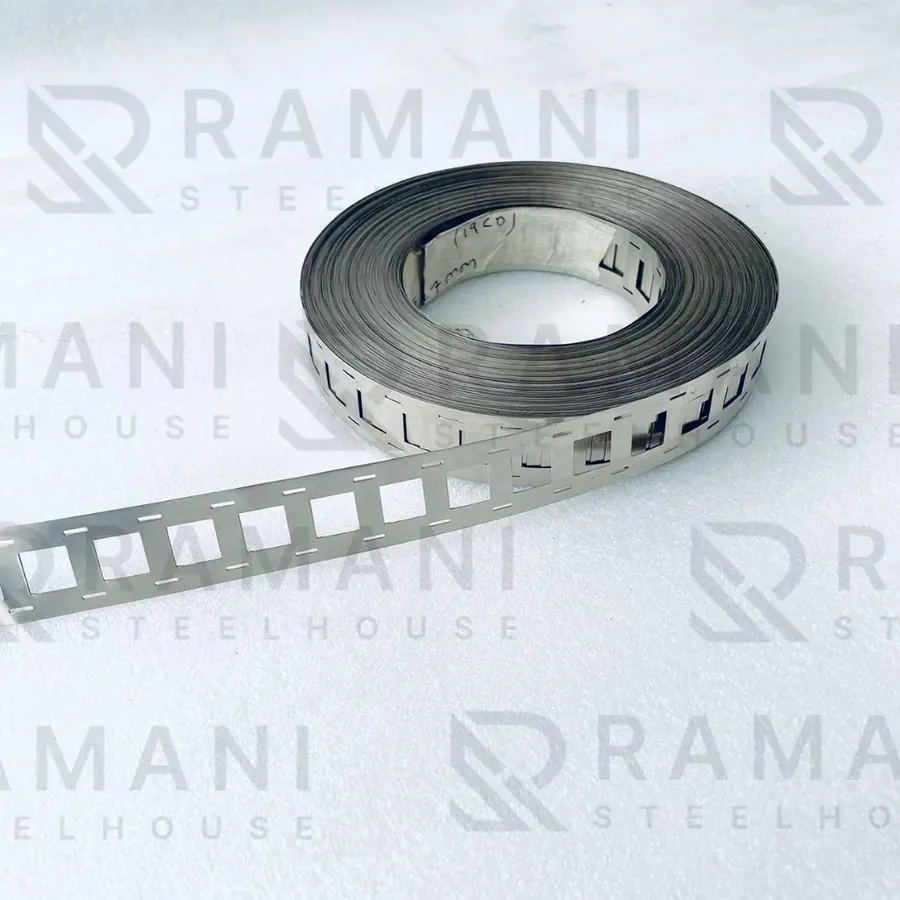 21700 2P H-type — Thickness: 0.20mm
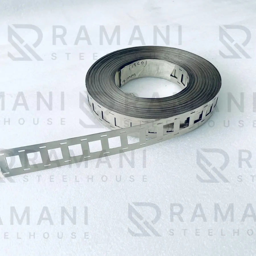 Ni 18650 2P H-Type Fuse Nickel Strip — Thickness: 0.15mm
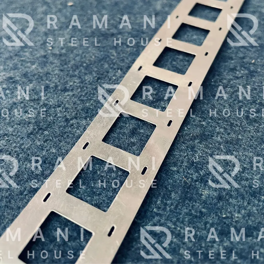 Ni 18650 2P H-Type Nickel Strip — Thickness: 0.15mm
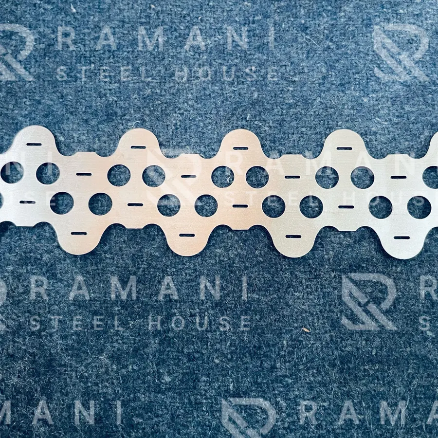 Ni 18650 2P ZIG-ZAG — Thickness: 0.20mm, Width: 44mm, 19mm CD, Length: Strip
Related guides
- 2P vs 3P vs 4P Nickel Strip: How Parallel Cell Count Changes Your H-Type Interconnect Design
- Nickel Strip vs Nickel Busbar: Key Differences and When to Use Each
- Zig-Zag vs H-Type Nickel Strip: Choosing the Right Interconnect Pattern for Your Battery Pack
- Fuse-Type vs Plain Nickel Strip: When Does a Battery Pack Actually Need a Built-In Fuse?
All nickel strip guides and technical articles · Nickel strip and busbar products