Zig-Zag vs H-Type Nickel Strip: Choosing the Right Interconnect Pattern for Your Battery Pack
.png?token=eyJraWQiOiJzdG9yYWdlLXVybC1zaWduaW5nLWtleV84ODdiMWJmNC1hOWFhLTQ2N2QtYTAwYy0zYTRkZTVjOTFlNWIiLCJhbGciOiJIUzI1NiJ9.eyJ1cmwiOiJJbWFnZXMvTmkgMTg2NTAgMlAgMTkuMG1tIENEIFppZyBaYWcgTm8gRnVzZSBUeXBlIFdhdGVybWFyayAoMykucG5nIiwic2NvcGUiOiJkb3dubG9hZCIsImlhdCI6MTc4Mjk4Mjc0NCwiZXhwIjozMDQ0NDIyNzQ0fQ.autp4UOmLLwgzQlviUcOI3NnRZy1NLdCLYHV8JW20IM)
Picking between zig-zag vs H-type nickel strip looks like a cosmetic choice on a datasheet, but the stamped pattern is actually a mechanical decision — it determines how much the interconnect can flex before a weld joint takes the strain. Get the pattern wrong for your application and you can pass every electrical test and still see weld fatigue failures months into field service.
In this guide:
- What makes zig-zag and H-type geometry different
- Why the stamped pattern is a mechanical decision, not just a look
- Selection criteria: zig-zag vs H-type
- Zig-zag vs H-type: side-by-side comparison
- Fuse-type zig-zag and H-type — when you need both together
- Common mistakes when choosing interconnect pattern
- FAQ
What Makes Zig-Zag and H-Type Geometry Different
Both patterns start from the same battery-grade nickel strip and do the same basic job — bridging cell tabs together into a parallel group and carrying current between groups. The difference is in how the metal is stamped between weld pads.
- H-type strip uses short, straight bridges between weld pads — essentially rigid rectangular links stamped with clearance holes sized to the cell can layout. Ramani Steel House stocks H-type strip across 18650 and 21700 cell formats in 2P, 3P, and 4P configurations.
- Zig-zag (honeycomb) strip uses a folded, serpentine bridge between weld pads instead of a straight run. That extra stamped-in length gives the bridge somewhere to flex. Our 18650 2P zig-zag strip is stamped this way specifically for cell layouts where that flex matters.
Visually the difference is obvious once you see both parts side by side; functionally, the zig-zag pattern trades a small amount of bridge stiffness and a slightly longer current path for mechanical compliance the straight H-type bridge doesn't have.
Parallel group count is a separate specification from pattern, and both geometries are available across the same group sizes. Whether you land on zig-zag or H-type, the question of how many cells to bridge per group — 2P, 3P, 4P, or a custom count — still applies on top of it; see our 2P vs 3P vs 4P interconnect design guide if you haven't settled that part of the layout yet.
Why the Stamped Pattern Is a Mechanical Decision, Not Just a Look
Cell "Breathing" and Repeated Thermal Cycling
Lithium-ion cells physically expand and contract slightly as they charge and discharge — sometimes called cell "breathing" — and that movement repeats every cycle for the life of the pack. Large Battery's technical overview of nickel strip function in battery packs describes this directly: strip connections need "expansion curves" or flexible sections built into the design to absorb this repeated volume change without the connection eventually snapping. A straight H-type bridge has very little give to absorb that movement — the strain goes almost entirely into the weld nugget. A zig-zag bridge's folded geometry can take up some of that movement as elastic flex in the strip itself, reducing the strain the weld has to absorb on every single cycle.
Vibration in Mobile Applications
The same logic applies to vibration, not just thermal cycling. A pack that lives in a vehicle, an e-bike, or any application with sustained mechanical shock puts continuous small stress on every weld joint in the pack. A rigid H-type bridge transmits more of that vibration energy straight into the weld; a zig-zag bridge's flex absorbs some of it mechanically before it reaches the joint. This is the same reasoning covered in our spot welding guide on why weld joint quality and interconnect geometry are linked, not independent variables — a well-made weld on a poorly-chosen geometry can still fail early under repeated mechanical load.
For medical-device and other high-reliability OEM applications, this isn't just a performance question — it can be a documented design input. If your product goes through a formal design verification or risk-management file, the interconnect's ability to survive its rated number of thermal cycles and its expected vibration profile without weld degradation is exactly the kind of failure mode that file needs to address. Choosing a pattern that already has mechanical margin for your duty cycle is easier to defend in that documentation than retrofitting a fix after a field failure.
Selection Criteria: Zig-Zag vs H-Type
Work through these questions before committing to a pattern:
- Will the pack see sustained vibration or shock in service? EV traction packs, e-mobility packs, and anything mounted on moving equipment are stronger candidates for zig-zag's flex. A stationary ESS or UPS pack in a fixed enclosure has far less vibration exposure to design around.
- How many charge/discharge cycles is the pack rated for? The more cycles a pack is expected to see over its service life, the more thermal-cycling flex exposure accumulates at every weld joint — and the more that favors a pattern with some built-in compliance.
- What's your available board/module footprint? Zig-zag's folded bridge takes up more lateral space per weld pad than a straight H-type bridge of the same pad spacing. Confirm your module layout has room for the pattern before committing to a BOM.
- Does the current path length matter for your sizing? The folded zig-zag path is marginally longer than a straight H-type bridge between the same two weld pads, which adds a small amount of resistance versus the shortest-path H-type equivalent. For most pack-level current requirements this is a minor factor next to thickness and width, but validate it with our current carrying capacity guide if your design is running close to its thermal margin.
- Does this group also need fault isolation? Pattern choice (zig-zag vs H-type) and fuse protection (fused vs plain) are two separate decisions that combine — see the fuse-type section below.
Zig-Zag vs H-Type: Side-by-Side Comparison
- Bridge geometry
- H-type: Short, straight, rigid link between weld pads
- Zig-zag: Folded, serpentine link between weld pads
- Mechanical compliance
- H-type: Minimal — strain transfers mostly to the weld
- Zig-zag: Higher — bridge flex absorbs some strain before the weld
- Best fit for vibration/cycling exposure
- H-type: Lower-vibration, fixed-installation packs (ESS, UPS)
- Zig-zag: Higher-vibration or high-cycle-count packs (EV, e-mobility)
- Footprint per weld pad
- H-type: More compact
- Zig-zag: Wider — needs clearance for the fold
- Current path length (same pad spacing)
- H-type: Shortest path
- Zig-zag: Marginally longer, folded path
Treat this as a starting framework rather than a substitute for your own vibration/cycle-life testing — the right pattern depends on your specific mounting, duty cycle, and thermal margin. Our interconnect sizing calculator can help check current path sizing for either pattern.
Fuse-Type Zig-Zag and H-Type — When You Need Both Together
Pattern (zig-zag vs H-type) and fault protection (fused vs plain) are independent specifications, and Ramani Steel House stocks fused versions of both. A fuse-type H-type honeycomb strip combines the rigid H-bridge with a stamped fuse neck; the catalog also includes zig-zag geometry with the same fuse-neck treatment for packs that need both mechanical compliance and per-cell fault isolation. Deciding whether you need the fuse neck at all is a separate question from geometry — our fuse-type vs plain nickel strip guide covers when that trade-off is worth making. Decide fault protection and mechanical pattern independently, then combine them: a vibration-exposed EV pack with strict single-cell fault isolation requirements may need fused zig-zag, not just one or the other.
Common Mistakes When Choosing Interconnect Pattern
Defaulting to H-type because it's more compact, without checking vibration exposure
Footprint is a real constraint, but it shouldn't be the only one. A compact H-type layout that fails weld fatigue testing after a few thousand vibration cycles costs far more to fix late than a slightly wider zig-zag layout would have cost to spec correctly up front.
Assuming pattern choice and fuse-type are the same decision
They're not. A team that needs fault isolation sometimes defaults straight to "fuse-type H-type" without separately asking whether the pack's vibration and cycling profile also calls for zig-zag's compliance — potentially needing both, not just one.
Copying pattern choice from a different pack's duty cycle
A pattern that was correct for a stationary ESS module doesn't automatically carry over to a vehicle-mounted pack reusing the same cell format. Re-evaluate vibration and cycling exposure for each application rather than defaulting to whatever pattern was used last time.
Not validating footprint before finalizing the BOM
Zig-zag's folded bridge needs more lateral clearance than an H-type bridge at the same pad spacing. Confirm your module layout physically accommodates the pattern you've chosen before tooling or ordering in volume.
Ignoring current path length in a tight thermal design
The difference is usually small, but if your design is already running close to its thermal margin, the marginally longer folded path in zig-zag strip is worth checking rather than assuming it's negligible.
Treating "we've always used this pattern" as validation
A pattern that's shipped without failures so far isn't the same as a pattern that's been validated for your current design's cycle count and vibration profile — especially if the cell format, mounting method, or duty cycle has changed since the pattern was first chosen. Field history on a different design is a data point, not a substitute for checking the current one.
Choosing between zig-zag and H-type nickel strip comes down to how much mechanical flex your pack's duty cycle actually demands — not just which one fits your layout most compactly. If you're specifying interconnect pattern for a new pack design, contact our engineering team with your cell format, vibration/cycling profile, and fault isolation requirements, or submit a product enquiry and we'll help match the right combination.
Frequently Asked Questions
Is zig-zag nickel strip always better than H-type?
No — it's better suited to applications with meaningful vibration or high cycle counts, not universally superior. H-type remains the more compact, lower-cost option for fixed-installation packs like stationary ESS or UPS units with limited vibration exposure.
Does zig-zag pattern reduce how much current the strip can carry?
Not directly from the pattern itself, but the folded path is marginally longer than the shortest H-type route between the same two weld pads, which adds a small amount of resistance. For most designs thickness and width dominate the current-carrying calculation; validate with our current carrying capacity guide if your design is running close to its thermal margin.
Can I get zig-zag and fuse-type protection on the same strip?
Yes — pattern (zig-zag vs H-type) and fault protection (fused vs plain) are independent specifications, and both can be combined. Ramani Steel House stocks fuse-type strip in honeycomb geometry for applications that need both mechanical compliance and per-cell fault isolation.
How do I know if my application has enough vibration to justify zig-zag?
If the pack is mounted on moving equipment — an EV, an e-bike, industrial mobile equipment — that's a strong signal to evaluate zig-zag. Stationary installations like ESS cabinets or UPS enclosures typically see far less vibration and are more often well served by H-type.
Does the parallel group count (2P/3P/4P) change with pattern choice?
No, group count is a separate specification — both zig-zag and H-type are available across standard parallel group sizes. See our 2P vs 3P vs 4P interconnect design guide for how to size that part of the layout independently of pattern.
What should I check before finalizing a zig-zag layout?
Confirm your module has the lateral clearance the folded bridge needs — it takes up more space per weld pad than an equivalent H-type bridge — and validate the design against your actual vibration and thermal-cycling profile rather than assuming compliance is "free."
Products covered in this article
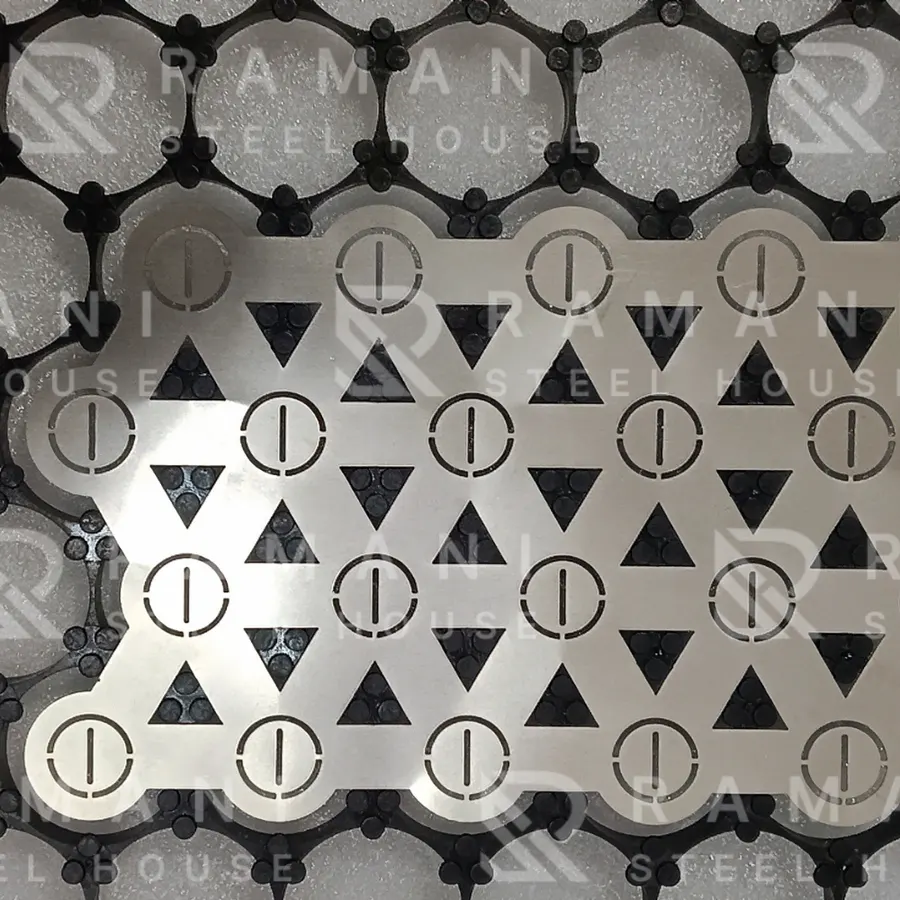 Ni Fuse-Type 18650 — Zig-Zag Honeycomb — Thickness: 0.15mm
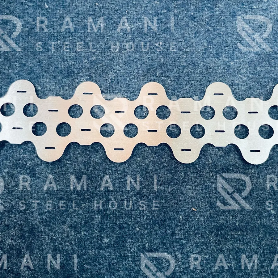 Ni 18650 2P ZIG-ZAG — Thickness: 0.20mm, Width: 44mm, 19mm CD, Length: Strip
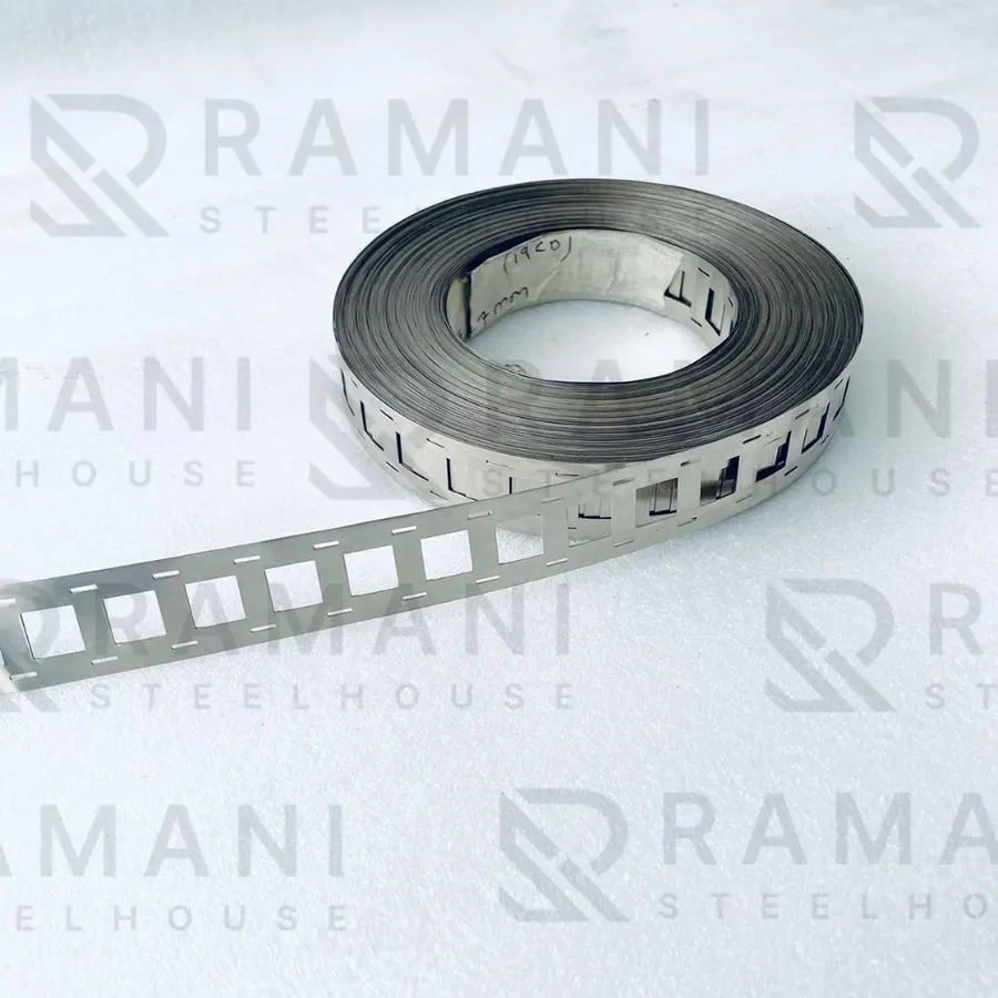 21700 2P H-type — Thickness: 0.20mm
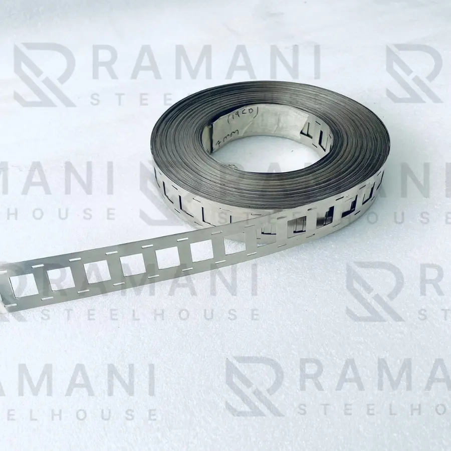 Ni 18650 2P H-Type Fuse Nickel Strip — Thickness: 0.15mm
Related guides
- Nickel Strip vs Copper Busbar: How to Choose the Right Interconnect Material for Lithium-Ion Battery Packs
- Fuse-Type vs Plain Nickel Strip: When Does a Battery Pack Actually Need a Built-In Fuse?
- Nickel Strip Pricing Guide: What Determines Cost for Bulk Battery Pack Orders
- 2P vs 3P vs 4P Nickel Strip: How Parallel Cell Count Changes Your H-Type Interconnect Design
All nickel strip guides and technical articles · Nickel strip and busbar products