Nickel Strip Current Carrying Capacity: An Engineer's Guide to Safe Battery Pack Design
.jpg?token=eyJraWQiOiJzdG9yYWdlLXVybC1zaWduaW5nLWtleV84ODdiMWJmNC1hOWFhLTQ2N2QtYTAwYy0zYTRkZTVjOTFlNWIiLCJhbGciOiJIUzI1NiJ9.eyJ1cmwiOiJJbWFnZXMvSCBUeXBlIDIxNzAwIENEIDIyLjUgbW0gWCA0MCBtbSAoNSkuanBnIiwic2NvcGUiOiJkb3dubG9hZCIsImlhdCI6MTc4MzQyMDkyNywiZXhwIjozMDQ0ODYwOTI3fQ.AYQIVh3arJIvBBq7U9qHZhCtwV9ZLiTfitmp12KAPjk)
Ask ten battery pack engineers "how many amps can this nickel strip carry?" and you will get ten different answers — because unlike copper wire, there is no universal ampacity chart for nickel strip. Thickness, width, weld spacing, pack ventilation, and duty cycle all change the answer. Guessing wrong means either an over-engineered, overpriced pack or a strip that overheats at the exact cell tab that holds your battery together.
This guide walks through the actual engineering method — resistivity, cross-sectional area, and Joule heating — using real dimensions from our own ASTM B162 certified nickel strip range, so you can size a strip or busbar connection correctly instead of copying a number from a supplier's marketing page.
In This Guide
- Why nickel and copper ampacity charts are not interchangeable
- The resistivity, cross-section, and Joule heating method
- A worked example using real 18650 zig-zag strip dimensions
- Why surface area matters as much as cross-section
- Continuous vs. pulse current and duty cycle
- One thick strip or two strips in parallel?
- Why fuse-type and zig-zag strips deliberately trade away ampacity for safety
- H-type vs zig-zag vs honeycomb vs plain strip: a practical comparison
- Spot welding and contact resistance — the factor most calculators ignore
- When to move from strip to a busbar-style interconnect
- A selection checklist and the most common sizing mistakes
- Industry standards worth knowing
Why Nickel and Copper Ampacity Charts Are Not Interchangeable
Most current-carrying-capacity charts in circulation — including the well-known IPC-2152 guidance used for PCB copper traces — are built around annealed copper, which has a resistivity of roughly 1.7 microhm-cm at room temperature (the basis of the International Annealed Copper Standard). Commercially pure nickel used in battery strip, Nickel 200 and its low-carbon variant Nickel 201, has a published resistivity of approximately 9.5 microhm-cm at room temperature according to Special Metals' technical data for Nickel 200/201.
That means, cross-section for cross-section, nickel strip dissipates roughly five to six times more heat per amp than copper. Applying a copper ampacity table directly to a nickel interconnect will significantly understate the temperature rise. This is precisely why nickel is chosen for battery tabs for its weldability and corrosion resistance rather than for raw conductivity — and why the sizing has to be calculated for nickel specifically, not borrowed from a copper reference.
The Engineering Method: Resistivity, Cross-Section, and Joule Heating
The starting point is basic conductor theory, applied honestly rather than reduced to a lookup table:
R = (rho x L) / A

where:
R     = DC resistance of the strip segment (ohms)
rho   = resistivity of the nickel grade (ohm-meters)
L     = current path length between weld points (meters)
A     = cross-sectional area = thickness x width (square meters)
Once you know the resistance of the segment, Joule heating tells you how much power it dissipates at a given current:
P = I^2 x R

where:
P = power dissipated as heat (watts)
I = current through the strip (amps)
This is only half the picture. The temperature rise that actually determines whether a strip is "safe" at a given current depends on how quickly that heat escapes — potting compound, airflow inside the pack enclosure, adjacent cell temperature, and duty cycle (continuous draw vs. short high-current pulses such as EV acceleration or fast charge). Two packs using the identical strip geometry can have very different safe current limits purely because of enclosure design. This is exactly why we recommend validating any calculated figure with a real thermal test on your specific assembly before finalizing a production design.
Worked Example: Real 18650 Zig-Zag Strip Dimensions
Rather than use a hypothetical strip, let's calculate using the actual published dimensions of our Ni 18650 2P Zig-Zag (No Fuse Type) strip: 0.20mm thickness, 44mm width, with a 19mm center distance between adjacent cell contact points.
Cross-sectional area:
A = 0.20mm x 44mm = 8.8 mm^2 = 8.8 x 10^-6 m^2

Path length:
L = 19mm = 0.019 m

Resistivity (Nickel 200/201, ~20C):
rho = 9.5 x 10^-8 ohm-m

Resistance:
R = (9.5 x 10^-8 x 0.019) / 8.8 x 10^-6
R = ~0.000205 ohms (0.205 milliohms)

Power dissipated at different currents:
  10A -> P = 10^2 x 0.000205 = 0.021 W
  20A -> P = 20^2 x 0.000205 = 0.082 W
  30A -> P = 30^2 x 0.000205 = 0.185 W
Notice the quadratic relationship — doubling the current roughly quadruples the heat generated in the bulk strip. On paper, the bulk strip resistance alone looks small. In practice, this is deliberately incomplete: it ignores the two spot-weld joints at either end, which we cover below, and it is only for a single interconnect — a real pack has this repeated at every cell tab, with heat accumulating in a confined enclosure.
Surface Area Matters as Much as Cross-Section
Resistance calculations tell you how much heat a strip generates. They don't tell you how quickly that heat leaves the strip — and that depends heavily on shape, not just cross-sectional area. A wide, thin strip has a much larger surface area exposed to surrounding air (or potting compound) than a thick, narrow strip or a round wire of the identical cross-sectional area. More exposed surface area means faster convective and conductive heat loss, which means a lower steady-state temperature for the same dissipated power.
This is one of the practical reasons nickel battery interconnects are manufactured as flat, wide strip rather than round wire in the first place: for a given amount of copper-equivalent conducting cross-section, the strip geometry cools faster inside a densely packed battery enclosure where airflow is limited. It's also why simply increasing thickness to add ampacity has diminishing returns compared to increasing width — a thicker strip adds cross-section (lowering resistance) but adds proportionally less surface area than a wider one, so past a certain point, widening a strip cools the connection more effectively per gram of nickel used than thickening it does.
Continuous vs. Pulse Current: Why Duty Cycle Changes the Answer
A strip that runs cool under a steady 10A draw can still overheat under repeated 40A pulses if the pulses are long enough or frequent enough relative to the strip's thermal mass. This matters directly for the applications we discuss in our EV battery pack guide — acceleration current spikes and fast-charge current profiles are pulsed loads, not continuous ones, and a strip sized purely against a continuous-current assumption can be caught out by them.
The underlying reason is thermal mass and cooldown time. Joule heating (P = I^2 x R) happens instantly with current, but temperature rise happens over time as heat accumulates faster than it can dissipate. A short pulse followed by a long rest period lets accumulated heat escape before the next pulse arrives, so the strip may handle a pulse current well above its continuous rating without exceeding a safe temperature. A pulse repeated too frequently, or one that's too long, doesn't get that recovery time and behaves thermally closer to a continuous load at the peak current. This is why any current rating you calculate needs to be qualified against your actual duty cycle — continuous, intermittent, or single-fault-event — rather than treated as one fixed number.
One Thick Strip or Two Strips in Parallel?
When a design needs more current capacity than a single strip comfortably provides but isn't yet at busbar territory, there are two common paths: increase the thickness/width of a single strip, or run two (or more) strips in parallel across the same joint. Both reduce total resistance, but they are not equivalent from a manufacturing or reliability standpoint.
A single thicker strip is simpler to weld and inspect, but very thick nickel strip becomes harder to spot-weld cleanly — higher thermal mass at the joint requires more weld energy, which increases the risk of expulsion or an inconsistent nugget. Parallel strips keep each individual weld within a well-controlled thickness range (in our case, typically 0.15mm-0.20mm for H-type and zig-zag grades), at the cost of needing twice the weld points and careful attention to ensure both strips carry a genuinely even current share. In practice, most production packs favor staying within a proven single-strip thickness band and adding a busbar-style connector once demand outgrows what parallel strips can reasonably handle — but for a moderate step up in current, parallel strips of your existing qualified thickness are often the lower-risk manufacturing choice.
Why Fuse-Type and Zig-Zag Strips Deliberately Trade Away Ampacity
Look closely at our Ni Fuse type 18650 honeycomb strip and the zig-zag geometry used above, and you'll notice neither uses a simple flat rectangular strip. The honeycomb and zig-zag cutouts intentionally narrow the cross-section at specific points.
This is not a manufacturing shortcut — it is a safety feature. A narrowed segment has less copper-equivalent cross-section, so by the same R = rho x L / A relationship, it has higher resistance and heats up faster than the surrounding strip under fault current. If a cell short-circuits, that narrow neck is designed to reach its melting point and open the circuit before the fault current can propagate through the rest of the pack. In other words, these designs sacrifice some ampacity headroom in exchange for a built-in, self-fusing safety mechanism — the strip pattern itself functions as a fuse, wired directly into the interconnect.
This is why "which strip has the highest current capacity" is the wrong question for a fuse-type design. The right question is whether the fuse point opens at the correct fault current for your pack's protection scheme, which is a function that should be validated against your BMS and protection design, not assumed from a datasheet number.
H-Type vs Zig-Zag vs Honeycomb vs Plain Strip: A Practical Comparison
Based on our current catalog specifications (ASTM/UNS designations as manufactured):
Product type          Thickness    ASTM / UNS grade        Typical role
--------------------  -----------  ----------------------  --------------------------------
Plain Nickel Strip     0.1-1.0mm   ASTM B162 / UNS N02200   General-purpose tab & interconnect,
                                                             widest thickness range for custom
                                                             current/weight tuning
H-Type Strip           0.15-0.20mm ASTM B162 / UNS N02201   Standard multi-cell (2P/3P/4P) tab,
                                                             low-carbon grade for clean spot welds
Zig-Zag Strip          0.20mm      ASTM B162 / UNS N02201   Honeycomb-style cell interconnect,
                                                             flexible layout for irregular cell
                                                             spacing
Fuse-Type / Honeycomb  0.15-0.20mm ASTM B162 / UNS N02201   Built-in overcurrent protection via
                                                             a narrowed fuse neck
Note the grade pattern: our plain strip is supplied to Nickel 200 (UNS N02200), while H-type, zig-zag, and fuse-type interconnects are supplied to Nickel 201 (UNS N02201) — the low-carbon variant. This isn't arbitrary. Nickel 201's lower carbon content reduces the risk of intergranular carbide embrittlement at spot-welding temperatures, which is exactly why it is the preferred grade wherever a strip is going to be spot-welded repeatedly across a production line, rather than used flat as a general connector.
Spot Welding and Current Capacity: The Contact Resistance Factor
Every calculation above covers the bulk resistance of the strip itself. In a real battery pack, current also has to cross two resistance spot welds — one at each cell tab. Contact resistance at a spot-weld nugget is frequently the single largest resistance in the entire interconnect path, often exceeding the bulk strip resistance calculated above by a significant margin, and it is highly dependent on weld parameters: electrode force, current, dwell time, surface cleanliness, and nugget diameter.
This matters for current capacity because a strip that looks over-specified on paper can still run hot in production if weld quality is inconsistent. It's also why we cover weld behavior in depth in our Pure Nickel Strip vs Nickel Plated Steel comparison — the strip material and grade you choose directly affects how consistent your weld nugget resistance will be across a production run, which in turn affects the real-world current capacity of the finished pack, not just the strip in isolation.
When to Move from Nickel Strip to a Busbar-Style Interconnect
Strip works well at the cell tab, where the connection needs to be thin, flexible, and weldable. It stops being the right choice once several parallel cell groups funnel into a single module or pack-level output — at that point the accumulated current usually exceeds what a thin strip can dissipate at an acceptable temperature rise, and the interconnect needs a heavier, busbar-style cross-section instead.
If you're at that stage of pack design, don't guess at a thickness — talk to our engineering team with your parallel cell count, target continuous and peak current, and enclosure/cooling approach, and we'll help size the interconnect correctly rather than retrofitting a strip that was never meant to carry module-level current.
Selection Checklist: Matching Nickel Strip to Your Current Requirement
- Confirm your cell configuration (1P, 2P, 3P, 4P) — more parallel cells per tab means more current funneling through each interconnect
- Calculate bulk resistance for your actual weld-to-weld path length, not a generic strip length
- Separate continuous current requirements from peak/pulse requirements (fast charge, acceleration) — they call for different thermal margins
- Decide whether you need a built-in fuse point (zig-zag/honeycomb/fuse-type) or maximum ampacity (plain or H-type strip)
- Check ASTM/UNS grade against your welding process — Nickel 201 (N02201) for repeated spot welding, Nickel 200 (N02200) where general conductivity matters more than weld cycles
- Validate your calculation with an actual thermal test under representative pack conditions before locking the design
- Plan for a busbar-style transition once parallel current accumulates beyond single-strip territory
Common Mistakes Engineers Make When Sizing Nickel Strip
- Applying a copper ampacity chart directly. Nickel's resistivity is roughly five to six times higher than copper's — the same chart will understate heating.
- Ignoring parallel cell count. A strip sized for a single cell's output current will run hot the moment it's used on a 3P or 4P tab carrying the combined current of three or four cells.
- Treating continuous and pulse current as the same problem. A strip that handles steady-state current fine can still overheat during repeated high-current pulses if thermal mass and cooldown time aren't accounted for.
- Assuming datasheet resistance without accounting for weld contact resistance. The bulk strip is often not the dominant resistance in the path — the weld nugget is.
- Skipping the thermal validation step. A calculation is a starting point, not a substitute for testing the actual assembly under real pack conditions.
Industry Standards Worth Knowing
While there is no single nickel-strip-specific ampacity standard, several references are worth keeping on hand when you document a design:
- ASTM B162, B16, B17 — material specifications for nickel plate/sheet/strip and nickel/nickel-alloy rod and wire, defining the grades (UNS N02200, N02201) referenced throughout this guide
- IPC-2152 — the standard reference methodology for conductor current-carrying capacity, built around copper; useful for the calculation method, not for nickel-specific numeric values
- IEC 62660 series — performance and reliability testing for lithium-ion traction battery cells, relevant when validating pack-level thermal behavior under load
- Battery University — a widely cited independent educational resource for battery pack design fundamentals, including cell interconnect behavior
Conclusion
There is no shortcut chart for nickel strip current capacity — but there is a reliable method: calculate bulk resistance from real geometry, apply Joule heating to estimate temperature rise, account honestly for weld contact resistance, and validate with a real thermal test before locking your design. Get the grade and geometry right, and a nickel strip interconnect will be exactly what it's meant to be: an unglamorous, completely reliable part of your battery pack that you never have to think about again.
If you're sizing an interconnect for a new pack design, our engineering team can review your cell configuration and current requirements directly — request a quote or contact us with your specification, and we'll help you choose between strip and busbar, and the right ASTM/UNS grade for your welding process.
Frequently Asked Questions
How much current can a nickel strip carry?
It depends on thickness, width, the length of the current path between welds, ambient cooling, and duty cycle — there's no single universal amp rating the way there is for copper wire gauge tables. Use R = (resistivity x length) / cross-sectional area and P = current^2 x R to estimate heating for your specific geometry, then validate with a thermal test on the actual weld joint before finalizing a production design.
Is nickel strip's current capacity lower than copper's?
Yes. Nickel 200/201 resistivity (about 9.5 microhm-cm) is roughly five to six times higher than annealed copper (about 1.7 microhm-cm), so for the same cross-section, nickel dissipates more heat per amp. This is why pure nickel strip is chosen at the cell tab for weldability and corrosion resistance rather than for raw conductivity, while high sustained current busbars often move to copper or nickel-plated copper.
Why do some nickel strips have a narrower "neck" cut into them?
Fuse-type, honeycomb, and zig-zag patterns intentionally narrow the cross-section at one point so that segment heats up and opens first during a fault, protecting the rest of the cell string. It is a deliberate design trade-off between raw ampacity and pack-level safety.
Should I use Nickel 200 or Nickel 201 strip for spot-welded battery tabs?
Nickel 201 (low-carbon, UNS N02201) is generally preferred for spot-welded interconnects because its lower carbon content improves weldability and reduces the risk of embrittlement at welding temperatures. Our H-type, zig-zag, and fuse-type interconnects are supplied to this grade, while general-purpose Plain Nickel Strip is supplied to Nickel 200 (UNS N02200).
When should I switch from nickel strip to a busbar-style interconnect?
Once the accumulated current per interconnect — commonly where multiple parallel cells funnel into a single module or pack-level output — exceeds what a thin strip can dissipate at an acceptable temperature rise, it's time to move to a busbar-style connector with a larger cross-section. Share your parallel cell count and target current with our engineering team and we'll help size it correctly.
Products covered in this article
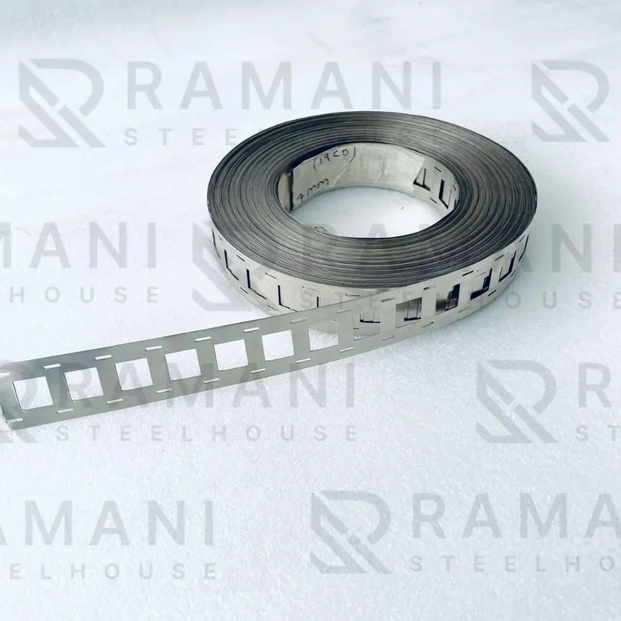 21700 2P H-type — Thickness: 0.20mm
 Copper Busbar
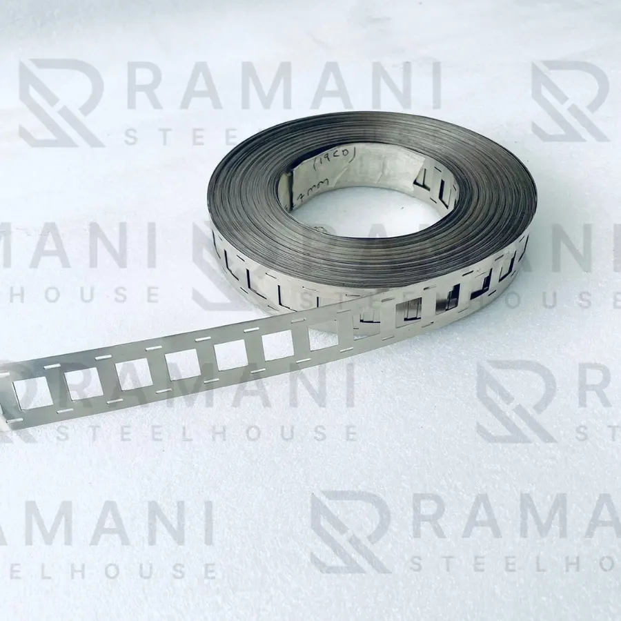 Ni 18650 2P H-Type Fuse Nickel Strip — Thickness: 0.15mm
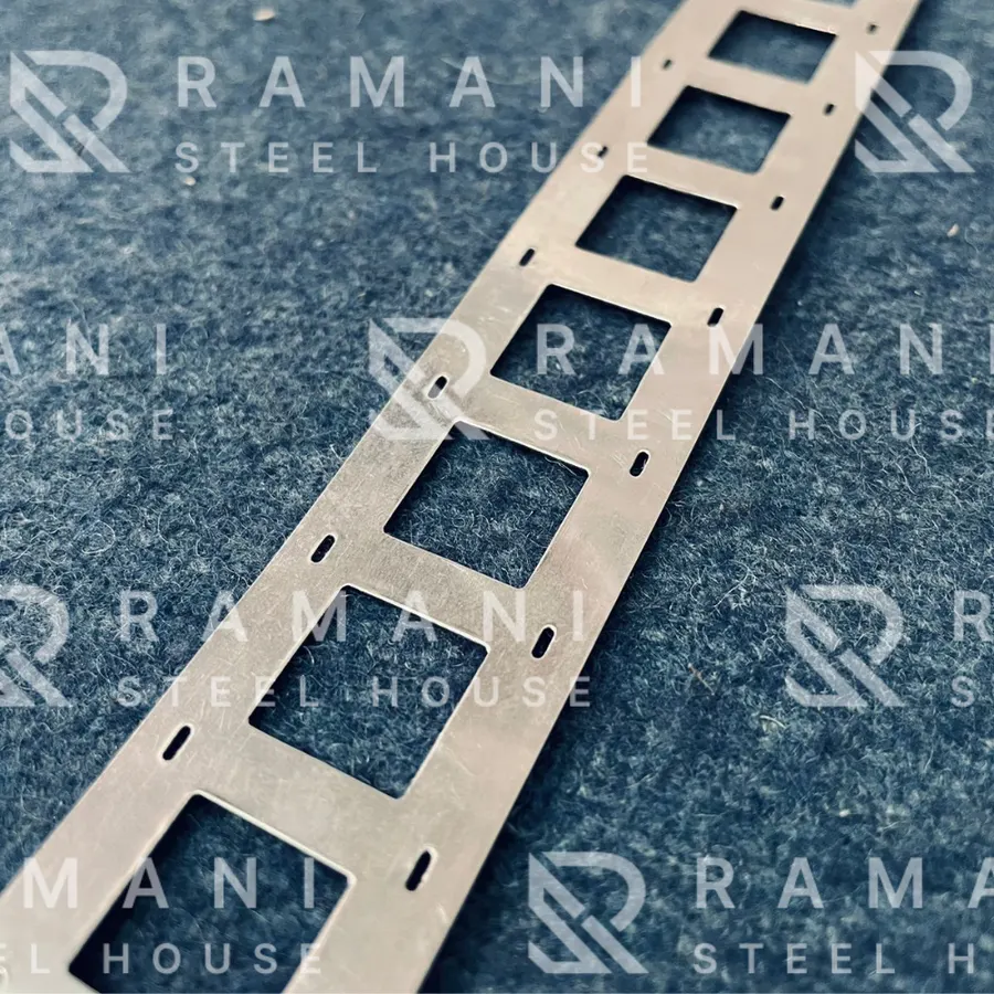 Ni 18650 2P H-Type Nickel Strip — Thickness: 0.15mm
Related guides
- Nickel Strip Pricing Guide: What Determines Cost for Bulk Battery Pack Orders
- Zig-Zag vs H-Type Nickel Strip: Choosing the Right Interconnect Pattern for Your Battery Pack
- Nickel Strip vs Copper Busbar: How to Choose the Right Interconnect Material for Lithium-Ion Battery Packs
- Fuse-Type vs Plain Nickel Strip: When Does a Battery Pack Actually Need a Built-In Fuse?
All nickel strip guides and technical articles · Nickel strip and busbar products