2P vs 3P vs 4P Nickel Strip: How Parallel Cell Count Changes Your H-Type Interconnect Design
.jpg?token=eyJraWQiOiJzdG9yYWdlLXVybC1zaWduaW5nLWtleV84ODdiMWJmNC1hOWFhLTQ2N2QtYTAwYy0zYTRkZTVjOTFlNWIiLCJhbGciOiJIUzI1NiJ9.eyJ1cmwiOiJJbWFnZXMvSCBUeXBlIDJQICYgIDNQICg0KS5qcGciLCJzY29wZSI6ImRvd25sb2FkIiwiaWF0IjoxNzgyOTgyODk1LCJleHAiOjMwNDQ0MjI4OTV9.jn5aEdccydN1fqpz8UF7xitdFlVA4B73lVTMstkpy1s)
Choosing between 2P vs 3P vs 4P nickel strip is not just a pack-layout decision — parallel group size changes how much current the interconnect actually carries, how many weld points share that current, and how a single bad cell behaves inside the group. Get it wrong and a pack that passes initial testing can still run hot or fail early in the field.
In this guide:
- What "2P," "3P," and "4P" mean on an H-type nickel strip interconnect
- Why parallel group size is a nickel strip design decision, not just a layout choice
- Selection criteria for matching H-type configuration to your pack design
- 2P vs 3P vs 4P: side-by-side comparison
- When to go beyond standard 2P/3P/4P — custom and coil-form options
- Common mistakes when specifying parallel-group interconnects
- FAQ
What "2P," "3P," and "4P" Actually Mean on an H-Type Interconnect
On a cylindrical-cell battery pack, cells are typically grouped in parallel (P) to reach the pack's required capacity and current rating, and those parallel groups are then connected in series (S) to reach the target voltage — the familiar "nS mP" nomenclature. An H-type nickel strip interconnect is stamped to bridge one parallel group of cells to the next: a 2P H-type strip bridges two cells per group, a 3P strip bridges three, and a 4P strip bridges four. Ramani Steel House's own catalog reflects this directly — 2P, 3P, and 4P H-type strip are all stocked as distinct parts for 18650 cells, with matching 2P and 4P options for 21700.
The strip's stamped geometry — tab spacing, bridge width, and the number of weld pads — is fixed to the parallel count it's designed for. That's why "just order more strip and cut it to size" doesn't work the way it might for coil-form product: the tab pitch has to match your cell can layout, and the bridge cross-section has to match the current that group is actually expected to carry.
Why Parallel Group Size Is a Nickel Strip Design Decision, Not Just a Layout Choice
Current Per Weld Point Scales With Group Size
Every cell in a parallel group contributes its share of the group's total current through its own weld to the H-type strip's bridge section. A 4P group carrying a given pack-level current per parallel group puts, in principle, roughly twice the current through the strip's bridge compared to a 2P group carrying the same per-cell current — because twice as many cells are feeding into it. That bridge section, and the weld nugget at each tab, has to be sized for the actual current it will see, not just for "the same strip we used on the last design." This is the same resistivity/cross-section/Joule-heating relationship covered in our nickel strip current carrying capacity guide — a 4P bridge is a different sizing problem than a 2P bridge, even on the same cell format and even at the same strip thickness.
Cell format compounds this. On our own catalog, 18650 H-type strip is supplied at 0.15mm thickness while 21700 H-type strip steps up to 0.20mm — a real, deliberate difference reflecting that 21700 packs are typically built for higher per-cell current draw than 18650 packs, on top of whatever parallel-group current the bridge already has to carry. In other words, cell format and parallel count are two separate inputs into the same sizing decision, not substitutes for each other: a 4P bridge on 21700 cells is a different design problem than a 4P bridge on 18650 cells, even before you factor in the parallel group's current sharing behavior.
Cell-to-Cell Current Sharing Isn't Perfectly Even
The simplest assumption — that a 4P group splits current evenly, one-quarter to each cell — only holds if all four cells have matched internal resistance. In practice they don't. Battery University's discussion of series and parallel configurations (BU-302) and cell matching (BU-803a) documents that even small differences in internal resistance between cells connected in parallel cause current to split unevenly between them, with the lower-resistance cell absorbing a disproportionate share. The practical implication for interconnect design: the bridge and weld joints in a larger parallel group need enough margin to handle a cell taking more than its "fair share" of current, not just the theoretical even split. This is one of the reasons cell sourcing and matching discipline matters as much as the interconnect spec itself.
Selection Criteria: Matching H-Type Configuration to Your Pack Design
Work through these in order when deciding between 2P, 3P, and 4P (or a custom count):
- Target capacity and continuous discharge current per parallel group. This is set by your cell's rated capacity and continuous discharge rating, multiplied by how many cells you put in parallel — work backward from your pack's power requirement to the minimum parallel count, then check whether a standard 2P/3P/4P part meets it or whether you need to go higher.
- Cell format (18650, 21700, or 32650). Tab pitch and bridge width are format-specific — an H-type strip stamped for 18650 cans will not line up correctly on a 21700 or 32650 layout. Confirm the strip's dimensions match your can diameter before finalizing a BOM.
- Fault tolerance requirements. A larger parallel group behind a plain (non-fused) strip means a single internally shorted cell can be fed fault current by every other cell in that group through the shared bridge. If your design needs each cell isolated from a neighbor's fault, compare plain H-type against a fuse-type honeycomb neck — see our fuse-type vs plain nickel strip guide for when that trade-off is worth it.
- BMS sensing granularity. Series-connected parallel groups are usually where your BMS takes its voltage taps. A higher parallel count per group means fewer total taps for a given cell count, which simplifies BMS wiring but also means the BMS can only see problems at the group level, not the individual cell level.
- Weld process capability. More welds per group (higher P count) means more weld cycles per module on the production line. Confirm your welder's electrode reach and duty cycle can handle the added weld density before committing to a higher parallel count purely to reduce part count elsewhere.
2P vs 3P vs 4P: Side-by-Side Comparison
- Cells bridged per group
- 2P: 2 cells
- 3P: 3 cells
- 4P: 4 cells
- Weld points per group
- 2P: 2 welds
- 3P: 3 welds
- 4P: 4 welds
- Current per bridge (for equal per-cell current)
- 2P: Lowest of the three
- 3P: Mid
- 4P: Highest of the three
- BMS voltage taps needed
- 2P: Most (finest granularity)
- 3P: Fewer
- 4P: Fewest (coarsest granularity)
- Typical fit
- 2P: Lower-current packs, tighter fault isolation
- 3P: Mid-power packs, balancing part count vs. granularity
- 4P: Higher-current packs, fewer parallel groups needed
Treat this as a starting framework, not a substitute for your own current and thermal calculation — actual bridge sizing depends on your specific cell's discharge rating and your pack's duty cycle. Use our interconnect sizing calculator to check a specific configuration.
When to Go Beyond Standard 2P/3P/4P — Custom and Coil-Form Options
Standard 2P, 3P, and 4P H-type parts cover the large majority of cylindrical pack designs, but two situations call for something else:
- Parallel counts above 4P, or non-standard cell pitch. High-capacity ESS modules sometimes run parallel groups larger than a standard catalog part supports, or use a cell pitch that doesn't match a stock stamping. This is a custom-tooling conversation — start with the details on our product enquiry form so engineering can confirm feasibility before committing to tooling.
- Non-standard layouts you'll form yourself. If your parallel groups don't map to a simple linear H-bridge — irregular can spacing, mixed cell formats in one module, or a layout your own stamping/forming process will handle — coil-form Plain Nickel Strip gives you the base material to cut and form to your own geometry.
Common Mistakes When Specifying Parallel-Group Interconnects
Sizing the bridge for average current, not the group's actual current
A 4P bridge needs to be evaluated against the current that specific group carries — not the per-cell current used to size a 2P design elsewhere in the same pack. Copying a bridge width or thickness across parallel counts without re-checking the math is a common source of under-sized interconnects.
Assuming perfectly even current sharing
As covered above, real cells don't split current perfectly evenly in a parallel group. Designing to the theoretical even split with no margin leaves no headroom for normal manufacturing variation in internal resistance.
Mixing cell formats or vendors within one parallel group without matching
Different cells — even nominally the same format from different lots or vendors — can have meaningfully different internal resistance. Mixing them in a parallel group makes uneven current sharing worse, independent of how well the interconnect itself is sized.
Choosing parallel count to minimize part count instead of matching current requirements
Going to a higher P count purely to reduce the number of series groups (and BMS taps) trades away sensing granularity and increases per-bridge current. That trade-off should be a deliberate design decision, not a default.
Ignoring fault isolation until late in the design
Whether a parallel group needs a fused neck is easier to decide before your interconnect tooling is locked in than after. If fault isolation between cells in a group matters for your application (medical devices, aerospace, or anywhere a single-cell fault propagating through the group is unacceptable), evaluate fuse-type strip early.
Getting parallel group size and interconnect sizing right the first time avoids a redesign after your first thermal test. If you're specifying an H-type nickel strip for a new pack — standard 2P/3P/4P or a custom parallel count — contact our engineering team with your cell format, target current, and cell count, and we'll help match the right configuration.
Frequently Asked Questions
What does "2P," "3P," or "4P" mean on a nickel strip interconnect?
It's the number of cells connected in parallel that a single H-type strip bridges — a 2P strip bridges two cells, 3P bridges three, and 4P bridges four. It's the "P" in the common "nS mP" pack notation, where "S" describes how many of those parallel groups are then connected in series.
Does a 4P nickel strip need to be thicker than a 2P strip?
Not automatically — it depends on the actual current through the bridge, which is a function of both parallel count and per-cell current, not parallel count alone. A 4P bridge carrying the same per-cell current as a 2P bridge will generally see more total current through its cross-section and needs to be sized accordingly; validate with the resistivity/cross-section method in our current carrying capacity guide rather than assuming a fixed multiplier.
Why do 21700 H-type strips use a different thickness than 18650 H-type strips?
On our catalog, 18650 H-type strip is 0.15mm and 21700 H-type strip is 0.20mm, reflecting that 21700 packs are typically designed for higher per-cell current than 18650 packs. Cell format and parallel group size are separate inputs into interconnect sizing, and both matter.
Do cells in a parallel group really share current evenly?
Not perfectly. Battery University's coverage of parallel battery configurations and cell matching (BU-302, BU-803a) documents that differences in internal resistance between cells cause current to split unevenly, with lower-resistance cells taking a larger share — which is why interconnect sizing and cell sourcing/matching both affect reliability.
When should I use fuse-type instead of plain H-type strip on a parallel group?
Consider fuse-type when a single cell fault in the group needs to be isolated from its neighbors rather than allowed to draw fault current through the shared bridge — common in medical, aerospace, or other applications where fault propagation within a parallel group is unacceptable. See our fuse-type vs plain nickel strip guide for the full trade-off.
What if I need a parallel count higher than 4P, or a non-standard cell pitch?
That's typically a custom tooling conversation rather than a catalog part — share your cell format, target parallel count, and pitch via our product enquiry form so engineering can confirm feasibility, or use coil-form Plain Nickel Strip if you'll be forming the interconnect yourself.
Products covered in this article
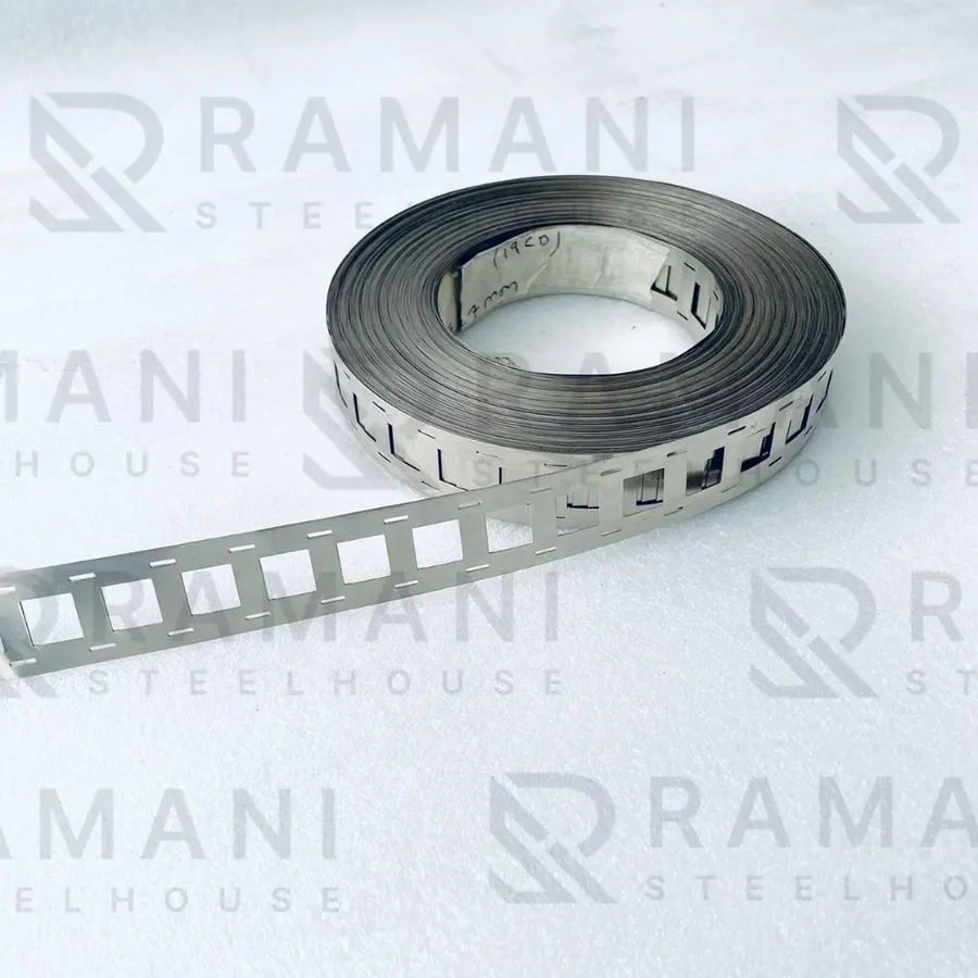 21700 2P H-type — Thickness: 0.20mm
 Ni 18650 2P H-Type Fuse Nickel Strip — Thickness: 0.15mm
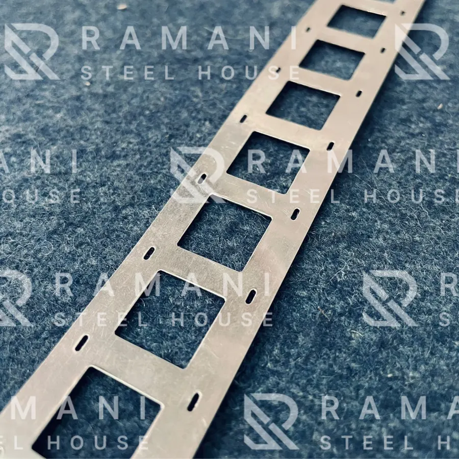 Ni 18650 2P H-Type Nickel Strip — Thickness: 0.15mm
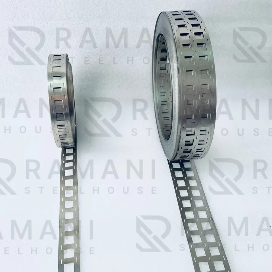 Ni 18650 3P H-type — Thickness: 0.15mm
Related guides
- 18650 vs 21700 Nickel Strip: What Changes When You Switch Cell Format
- Zig-Zag vs H-Type Nickel Strip: Choosing the Right Interconnect Pattern for Your Battery Pack
- Nickel Strip vs Copper Busbar: How to Choose the Right Interconnect Material for Lithium-Ion Battery Packs
- Fuse-Type vs Plain Nickel Strip: When Does a Battery Pack Actually Need a Built-In Fuse?
All nickel strip guides and technical articles · Nickel strip and busbar products