How to Size Nickel Strip for a Battery Pack: Step by Step, With a 13S4P Example
Ramani Steel House ·
To size nickel strip, take your continuous and peak current, divide it by the cells in parallel, then calculate the strip's resistance from its narrowest cross-section and path length (R = rho x L / A) and its heat (P = I squared x R). Add the welds, which the formula leaves out, check the peak and duty cycle, then confirm with a thermal test on a real assembly.
Sizing nickel strip comes down to one question: at the current your pack really draws, does the strip stay cool enough, at its welds as well as along its length? There is no single ampacity chart, because the answer depends on the strip's narrowest cross-section, the path length between cells, the welds and the duty cycle. This guide gives the method in seven steps and works it through for a 13S4P pack.
The example pack (replace these with your own numbers)
- 13S4P: 13 groups in series, 4 cells in parallel per group, 18650 cells (52 cells in all)
- Controller limit: 30 A continuous, 40 A peak
- Nominal pack voltage: about 47 V (13 x 3.6 V)
- Candidate strip: 44 mm wide with 19 mm between cell contacts, in 0.15 mm or 0.20 mm thickness (the strip dimensions are those of the zig-zag strip in our current-carrying capacity guide)
These are illustrative assumptions. The point is the method, so swap in your own current, cell count and strip geometry.
Building an e-bike or e-rickshaw pack? Our guide to nickel strip for e-rickshaw and e-bike battery packs covers the thickness and pattern choices for those loads.
Step 1: Start from your real currents
Take the continuous and peak current from the controller, charger and BMS limits, not from a cell's maximum rating. You need both: continuous current sets the steady temperature, and peak current sets the worst case. Here that is 30 A and 40 A.
Step 2: Work out the current per cell and per weld
With even sharing across a parallel group, each cell carries the pack current divided by the number of cells in parallel: 30 ÷ 4 = 7.5 A per cell, and 40 ÷ 4 = 10 A at peak. Check those against the cell's datasheet before going further, because no strip can fix an overloaded cell. With two weld spots per cell tab, each spot carries about 3.75 A continuous (two spots per cell is an assumption; set yours from your own welding trials).
Step 3: Find the narrowest cross-section on the path
Resistance is set by the smallest cross-section the current has to pass through, not the full width of the strip. Holes, cut-outs and fuse necks all reduce it. To keep the arithmetic traceable we use the full 44 mm width here, so treat the results as a best case: real strip, with its cut-outs, will be worse. Cross-section is thickness times width:
- 0.15 mm × 44 mm = 6.6 mm²
- 0.20 mm × 44 mm = 8.8 mm²
Step 4: Calculate resistance and heat per link
For the current path between adjacent groups, R = ρ × L ÷ A, with ρ about 9.5 x 10^-8 ohm-metres and L = 19 mm. Heat is P = I² × R, and the voltage drop is V = I × R. The same pack, in two thicknesses:
| Strip | Cross-section | Resistance per link | Heat at 30 A | Heat at 40 A | Voltage drop at 30 A |
|---|---|---|---|---|---|
| 0.15 mm x 44 mm | 6.6 mm² | 0.273 milliohm | 0.246 W | 0.438 W | 8.2 mV |
| 0.20 mm x 44 mm | 8.8 mm² | 0.205 milliohm | 0.185 W | 0.328 W | 6.2 mV |
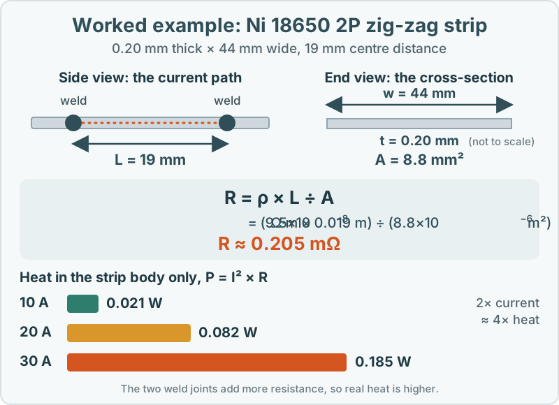
This pack has 12 series links, so at 30 A the strip bodies dissipate about 3.0 W in total with 0.15 mm strip and about 2.2 W with 0.20 mm, against roughly 1,400 W of pack power (47 V x 30 A). That is around 0.2%. The lesson is not that efficiency is a problem. It is that the loss is small overall and concentrated in a few places, which is why you size against a local hot spot rather than the total.
Step 5: Add what the formula leaves out: the welds
The calculation covers only the strip body. Every weld adds contact resistance that no formula predicts, so measure it: record the voltage drop across a welded joint at a known current in your own welding trials, and divide by the current to get its resistance. If a joint's resistance is comparable to the strip's, the welds rather than the strip set your temperature. Our spot welding guide covers what drives weld quality, and why nickel strip overheats shows how to tell a weld problem from a sizing problem.
Step 6: Check the peak and the duty cycle
Heat rises with the square of current, so the 40 A peak produces (40 ÷ 30)² = 1.78 times the heat of 30 A: 0.438 W against 0.246 W on the 0.15 mm strip. Whether that matters depends on how long and how often the peak lasts. A short pulse followed by a long rest lets the heat escape; the same peak held longer, or repeated sooner, does not. Size for the peak and the duty cycle together.
Step 7: Choose the pattern and thickness, then validate
Thickness is a trade-off: thicker strip lowers resistance but needs more weld energy and is harder to weld cleanly, so most packs stay within a thickness band their welding process already handles well. The pattern then follows the layout and the protection scheme:
| Your situation | Strip pattern |
|---|---|
| Standard 4P group-to-group links | H-type, for example the 18650 4P H-type strip |
| Irregular cell spacing, or a layout that needs flexibility | Zig-zag, for example the 18650 2P zig-zag strip (see zig-zag vs H-type) |
| No cell-level protection, and you want a fault contained at the tab | Fuse-type (see fuse-type vs plain strip) |
| A layout no standard pattern fits | A custom pattern cut to your pitch |
Then validate before you commit. Run the pack at its worst-case load and duty cycle with a thermocouple at a weld, mid-strip and on a neighbouring cell. Pull-test welds from the same batch. Only then freeze the design.
Order a sample first. Ramani Steel House supplies from a 5 kg minimum order, typically despatched within 7 days, with a material test certificate on request. Browse the catalogue, use the calculator to check weights and dimensions, or send your pack layout and current for a quotation.
Products covered in this guide
Order nickel strip in your exact size
Standard thicknesses from 0.10 to 0.30 mm and widths from 2 to 50 mm, or any size made to your drawing. Orders start at 5 kg.
Frequently Asked Questions
How many amps can nickel strip carry?
There is no single figure. It depends on the strip's narrowest cross-section, the path length between welds, the welds themselves, how well heat escapes and the duty cycle. Calculate resistance and heat for your geometry, then confirm with a thermal test on a real assembly.
Should I size nickel strip for continuous or peak current?
Both. Continuous current sets the steady temperature and peak current sets the worst case. Heat rises with the square of current, so a peak 33% above continuous produces about 78% more heat while it lasts.
Is a thicker nickel strip always better?
No. Thickness lowers resistance, but it adds less cooling surface than width, and thick strip is harder to weld consistently. Widening the strip, or running strips in parallel at a thickness you can weld reliably, is often the lower-risk route.
Can I use the same strip for 18650 and 21700 cells?
Not usually. The pattern is cut to the cell pitch, which differs between formats, so a strip made for one rarely lands correctly on the other. See our 18650 vs 21700 guide for what changes.
Why does the distance between cells matter for strip sizing?
Resistance rises in proportion to the length of the current path. For the same strip, a wider cell pitch means a longer path between welds and therefore more resistance and more heat.
More nickel strip guides
Related articles
Related categories
All nickel strip guides · Technical articles · Nickel strip and busbar products